

Troubleshoot a Printed Circuit Board Prototype
When something stops working on a printed circuit board prototype it is important to figure out what the cause is as soon as possible. This will help minimize expensive rework later on, as well as avoid lost time and money due to a costly error. Most of the time these errors can be traced back to a broken connection. Whether it is the result of physical damage or design error, these issues are best caught early in the process.
PCBs are complex pieces of equipment with layers of copper traces, different signal attributes and numerous components. These connections are made through solder joints and conductive pins or pads. There are also varying types of components on a printed circuit board prototype, and some have unique specifications such as temperature ratings. All of these factors can affect how the circuit board performs. In order to troubleshoot a prototype it is crucial to have access to the schematic and the PCB layout. This will allow you to look at all of the connections and see if any are broken. It may also be helpful to use a multimeter set to ohms measuring or buzzer mode to check for shorts and open circuits.
Some of the most common problems are shorts and opens in the circuit. A short is an unintended connection between two points and can disrupt the functionality of a PCB’s final product. This can be caused by a number of things, such as poor design or human error (design blind spots).
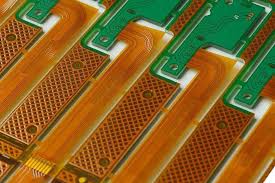
How to Troubleshoot a Printed Circuit Board Prototype
Another common issue is physical damage, which can occur due to rough handling and dropping of the prototype or contamination from chemicals or dust. This can lead to cracks in the components or damage to the solder joints, solder masks and traces on the circuit board. Lastly, it is a good idea to keep wires from being stressed or pulled too hard as this can cause them to break. Keeping them long enough to go from component to component and having some slack can help prevent this, and using a sensible color scheme for the wires is useful (such as red for positive, black for ground, etc). Using zip ties or spools of cable can also control and organize these wires.
Fortunately, there are ways to troubleshoot these issues on a prototype. One of the simplest is to compare a functioning prototype to the original schematic. This can reveal any glaring issues that need to be addressed before the prototype is produced.
A simple inspection with the PCB connected to power can also be beneficial in identifying issues. Physical component and connection errors often show up as hot spots on the circuit board, with specific areas becoming warmer than others. By comparing the circuit to the schematic and analyzing the voltage, current flow and waveforms on a multimeter it can be determined where the problem lies.
If there is a short in the circuit, it can be isolated by cutting the circuit board into sections and re-checking the net connections for that area. This method is effective, but a little tedious and can be difficult to follow on complex boards.